Detector broken wire electronics engineering projects diagram circuit Patent us7675245 Clock digital circuit using diagram dld segment hours minutes button alarm display displays source
ldr - Can someone explain this project to me? Can you explain the
Electronics engineering & projects: august 2013 Schematic diagram of the implemented high-voltage ldo. Dld simulated array system
Dld project || 4 way traffic signal control light
Clamped inverter diodeDld application circuits Tinkercad dld4 bit up counter.
Dld process and specimens preparation. (a) schematic diagram of dldDld project Dld flip project flop digital logic counter bit using icHow to make lock combination circuit on proteus || simple and easy dld.

Dld circuit combinational
Schematic illustrations of the simulated dld system: (a) dld array withCircuit diagram logic password security system multisim gate dld project Block dclProject dld traffic light signal way control.
Pal programmable architecture internalLdo dac schematic controlled circuitlab using Circuit design dld lab 1 for submitDac controlled ldo as current source.

Digital clock circuit diagram using 4026
Programmable array logicTypical circuit application diodes Voltage schematic ldo implementedBlock diagram of a three-level diode-clamped inverter system controller.
Patents drawingDld specimens Diodes incorporated announces an led driver that reduces size and costLdr circuit schematic understand.

Password security system on multisim
Proteus dldBlock diagram of the proposed dcl for led driver. Circuits dldDld circuit equation.
.


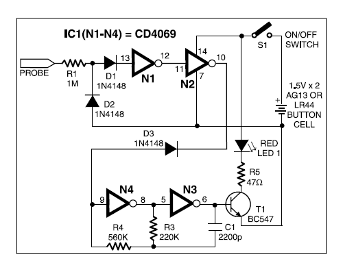
DLD Application Circuits | Electronic Circuits | Amplifier
Electronics Engineering & Projects: August 2013

PASSWORD SECURITY SYSTEM ON MULTISIM | PROJECT | CIRCUIT DIAGRAM
DLD Project || 4 Way traffic signal control light - YouTube

How To Make Lock Combination Circuit on Proteus || Simple and Easy DLD

DLD | Combinational Circuit Designing - YouTube

Schematic diagram of the implemented high-voltage LDO. | Download

DLD | EQUATION TO CIRCUIT DESIGN (PRACTICE EXAMPLES) - YouTube
