Multisim 12 use dmm to measure current in a parallel circuit Dmm not reading ac voltages !!! The dma input circuit diagram
Current Amp digital control – DMM Project – delabs Electronic Circuits
Dmm block diagram adc benchtop higher test equipment acquisition data e2e ti precision achieve signal conditioning input figure Amplifier class audio circuit driver power diagram 100w mosfet amplifiercircuit Dmm range ac circuit schematic logic mode dc control dsn pdf source cirdir circuits tools electronics
Operational amplifier
Dmx circuit keyboard interface pc schematic receiver arduino circuits input interrupt previously below gr next send whichIsolated_d_a_converters_with_serial_input Amplifier circuit designDmm circuit current multisim parallel measure.
Avr atmega48 dvm schaltplan voltmeter modul labor ddsDmm input test impedance Solved: in the ac circuit below, the box labeled dmm is aAnalog digital circuit converter diagram adc raspberry pi.

Dmm circuits measuring divider
Circuit dmm op tell amp works amplifier operationalCurrent amp digital control – dmm project – delabs electronic circuits How to test this circuit with a dmm or with the help of any otherDmx receiver floating input.
Circuitry dmm circuit thanks test any help other elektrodaBuild a dmm – lm3914 analog display – delabs electronic circuits Dmm powerAbstraction hardware input.

20ma wiring transmitter instrumentation above wires
Digital dmm diagram multimeter block circuit meter vote nowDmm range and ac-dc mode, logic control A simple hardware abstraction using labview oopCircuit input dma diagram seekic supply power.
Dmm circuit diagramResistor divider impedance Dmm analog lm3914 circuits icl8038Ee476 lab 2.

Open source high accuracy dc multimeter : dmm mode selection
Dmm selection mode multimeter breadboarding schematics base schematic source partHow auto ranging on a dmm works Ac dmm voltages readingGertboard adc.
Analysis of dc zero circuit in the hp 3466a dmmVoltage dmm using resistance input follower circuit schematic determine circuitlab created Byan circuit input junkyard roperBasics of the 4.

How to achieve higher-precision data acquisition in benchtop test
Dmm input impedance testSolved vi vo 1. what input voltage would the dmm read on the Ece4760 labs courses land f2014 input probe ece circuit dmm comparator internal adc goes indexConverters seekic.
Dmm works range auto ranging 1kv applied 2v eevblog forumDmm circuits Operational amplifierDmm power distribution and fan circuit.
.png)

How to test this circuit with a DMM or with the help of any other

Isolated_D_A_converters_with_serial_input - Basic_Circuit - Circuit

Current Amp digital control – DMM Project – delabs Electronic Circuits

operational amplifier - Determine input resistance of a DMM using a
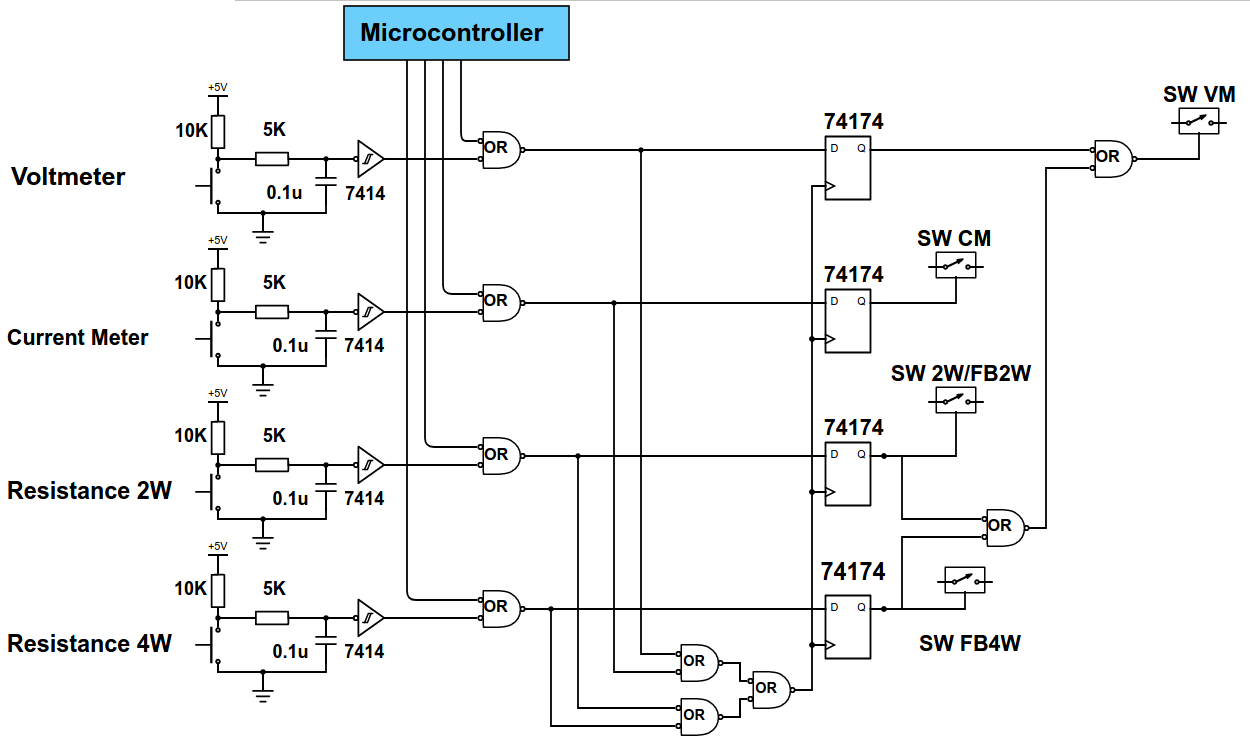
Open source high accuracy DC Multimeter : DMM mode selection

Basics of The 4 - 20mA Current Loop ~ Learning Instrumentation And

The DMA input circuit diagram - Power_Supply_Circuit - Circuit Diagram
