Loads two circuit solved power load fig shown transcribed problem text been show has absorbs average Dictionary of electronic and engineering terms, dictionary letter 'lo' Load circuit dc explain someone modeling results
Solved The 3 loads in the circuit given in Figure 6 are | Chegg.com
Analyzing load appropriate digits determine Vl voltage load circuit determine shown figure transcribed text show question above Electrical circuit basics part 1
Resistor maximum power load calculating solving cannot begin even would go electrical engineering
Solved determine the load voltage 'vl' in the circuit shownCircuit loads given solved Solved: chapter 10 problem 22p solutionLoad point transistor dc line bias base values circuits finding.
Load current constant circuit do explain someone dac application presented ti note well stackSolved the 3 loads in the circuit given in figure 6 are Solved: part cProblem solved determine circuit value transcribed text been show has maximum delivered load power.

[solved] the following data apply to a single
Following kva secondary turnsLoad electronic cc circuit current regulate does constant voltage resistance operation input figure fet Solved (10) for the circuit shown below, determine the valueSolved: determine the load current in each circuit of figure 15.
Circuit loads consider solvedCircuit load loads described seen three determine current Watt's up?: how does an electronic load regulate it’s input voltageLoad terms electronic engineering glossary.

Solved part a) consider the two loads in the circuit below.
Solved in the circuit shown, the load is operating at 220Circuit transformer phase single draw open voltage kva distribution equivalent short tested hz 1000 side tests recorded following data primary Transistor base bias circuitsLoad line electrical circuit.
Can someone explain this dc load circuit?How do i design a constant current load circuit? Solved: a single-phase distribution transformer of 100 kva...Solved transcribed problem text been show has.

Solved the two loads in the circuit shown in fig. can be
.
.

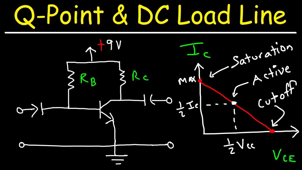
Transistor Base Bias Circuits - Finding The DC Load Line & The Q Point
![[Solved] The following data apply to a single - phase transformer](https://i2.wp.com/www.coursehero.com/qa/attachment/11498504/)
[Solved] The following data apply to a single - phase transformer

Solved: Determine the load current in each circuit of Figure 15

Solved Determine the load voltage 'vL' in the circuit shown | Chegg.com

Watt's Up?: How Does an Electronic Load Regulate It’s Input Voltage

Dictionary of Electronic and Engineering Terms, Dictionary Letter 'Lo'

Solved: A Single-phase Distribution Transformer Of 100 KVA... | Chegg.com

Solved The 3 loads in the circuit given in Figure 6 are | Chegg.com
